Hey, I am Mahdi.
I am currently a computer science student.
What are the conditions for network communication?
Devices need to be able to understand each other when communicating over networks. The same way humans need to understand the language spoken by their communication partner. Otherwise the received information couldn't be processed to react properly.
For network communication the devices and applications use network protocols. These are rules that dictate how communication should take place. What information needs to be transmitted and how the information has to be evaluated.
Now vendors that create hardware devices and applications need to follow the rules of these protocols when designing them. This allows vendor-independent communication, since all devices no matter who produced them follow the same rules and speak the same language now.
Without them each vendor would have to come up with their own idea for network communication, therefore only the devices of this same vendor could communicate.
We might compare it with rules for sports. Even if two teams of different countries face each other in a match, they still know how to behave thanks to the rules that act as guidelines. But if each country had their own rules for a specific sport, then both teams would have learned the sport with different rules which would only cause chaos on the game field and simply wouldn't work.
Why do wee need network layers?
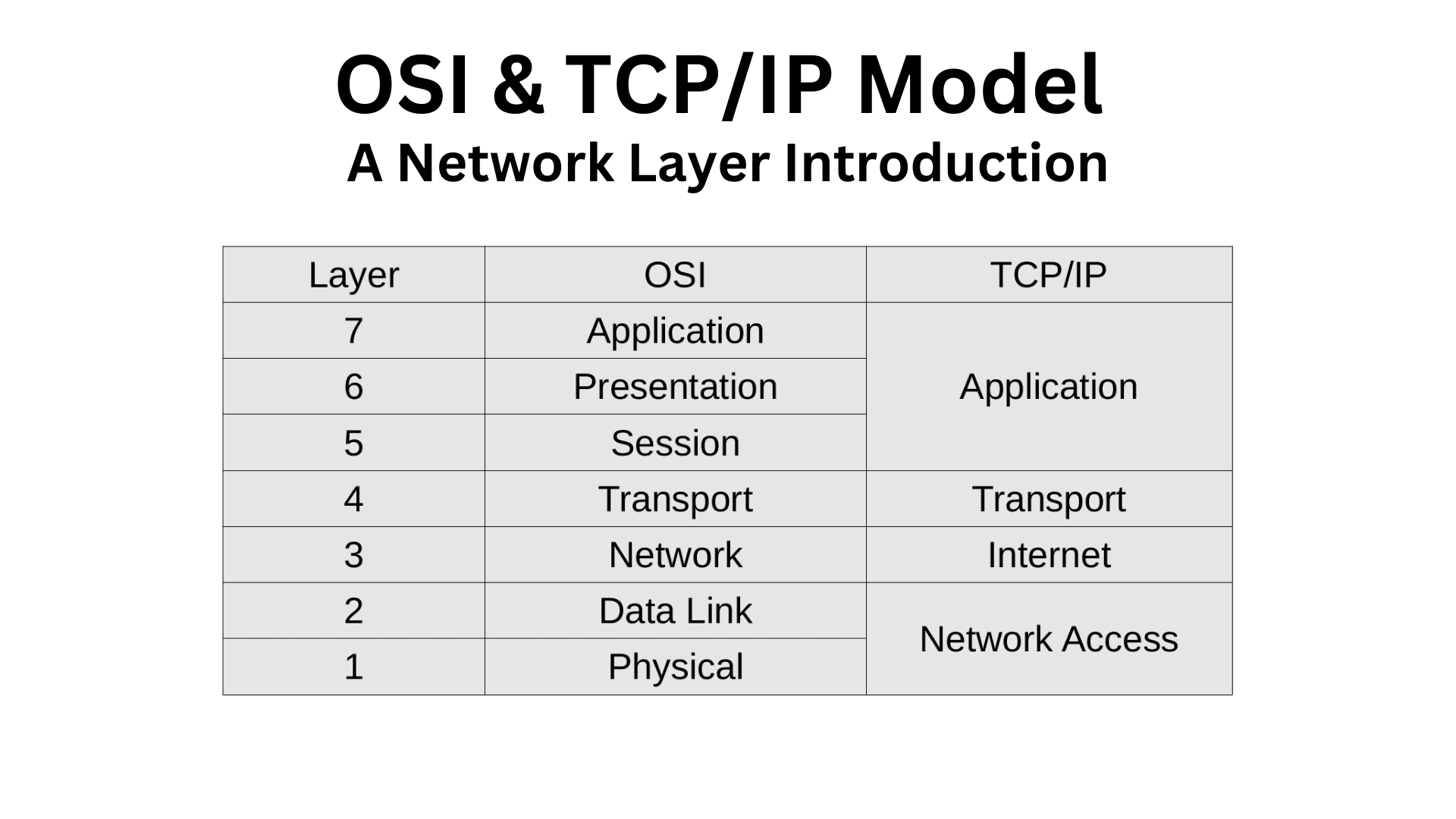
There are two network models available that are most referred when it comes to describing networks and their functions. These are the OSI and TCP/IP model. Both follow the same approach of dividing the network into layers.
In the previous section we did learn about protocols and rules. There are multiple network protocols available that operate on a different layer of these models. Thus each layer is responsible for handling different tasks and there are multiple protocols being used simultaneously when starting a network communication.
For example TCP (Transmission Control Protocol) and UDP (User Datagram Protocol) are protocols that both work at the Transport layer and their task is to establish a connection between two devices before data is sent.
With this layered approach not only are we able to take a closer look at the communication processes in more detail and understand them better, but in case of networking issues we are able to better pinpoint where those issues might come from and solve them.
While both models follow the same layering methodology, they differ in terms of layer number. The TCP/IP model describes the network with four layers, but the OSI model goes a step further an breaks the TCP/IP layers 1 and 4 into five additional layers, resulting in seven layers. As we can see from the cover image the layers 5, 6 and 7 of OSI can be mapped to the layer 4 of TCP/IP and the layers 1 and 2 of OSI can be mapped to the layer 1 of TCP/IP.
The TCP/IP model is more practical oriented and derives its name from the TCP and IP protocols, which serve as the foundational elements of the internet, since they were introduced before UDP. On the other hand, the OSI model provides a more theoretical perspective on networks, making it better suited for understanding network layer functions.
Short overview of layer functions

What happens with the data at each layer?

Data is also described as Protocol Data Unit (PDU). But when the data moves along the layers a new name will be assigned at different layers for better differentiation.
PDUs can have the following names: Bits, Frame, Packet, Segment (when transport protocol TCP is used), Datagram (when transport protocol UDP is used) and Data.
The following table presents a short overview.
| PDU Name | Layer |
| Data | Application, Presentation and Session |
| Segment [TCP], Datagram [UDP] | Transport |
| Packet | Network |
| Frame | Data Link |
| Bits | Physical |
A PDU consist of a body with the actual data and a header that contains information about how to handle the PDU at each layer. When data is sent, PDUs are passed down from the highest layer (Application) to the lowest layer (Physical). At each layer the PDU gets processed and new information gets added to the header. This is called encapsulation.
When data is received the data flow is in the opposite direction from lowest layer to highest layer until the data reaches the user. The additional PDU Header Information that have been added are now processed backwards at each layer and removed afterwards. Almost like peeling an onion layer by layer. This process is called de-encapsulation.
Let's look at it with an imaginary scenario. We work at a company and want to send a letter and put it in an envelope. The letter itself is our data and the envelope is our header. Before the envelope reaches the postman (the network media), it has to be passed down through different departments (the different layers). At each department our envelope with our letter in it is put in another envelope with new information added by the department. When the letter reaches the postman, it is nested into multiple envelopes. Now the postman delivers our letter to another company with the same structure as ours and passes it first to the department at the lowest hierarchy. They open the envelope, read the message relevant to them. Take the other envelopes out and pass them to the next higher layer, where they redo the process until the letter reaches the intended recipient.